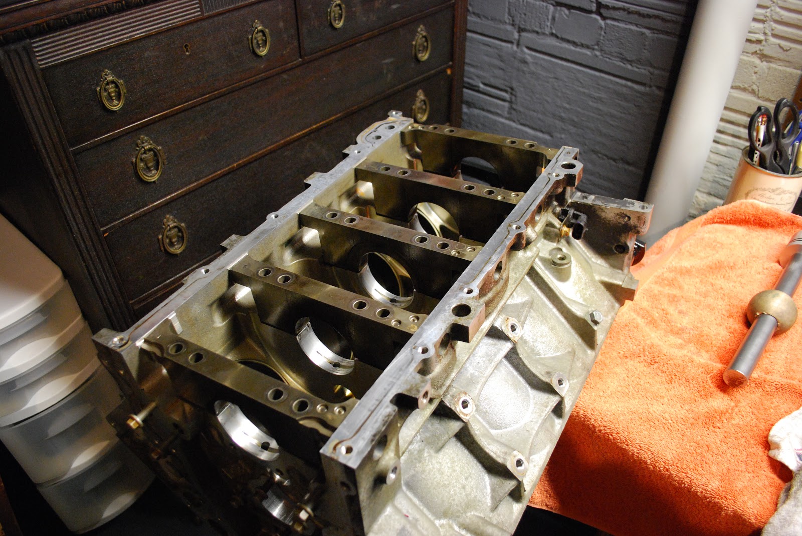
It seems that the last of my engine parts for the short block are in.
Callies Compstar LS1 6.125" Rods, Forged H-Beam with 7/16" ARP 2000 bolts
Diamond #11502 3.905" -1.66cc Flat top pistons
Diamond plasma-moly ring set
Clevite main + rod bearings, stock clearances
Took a bit of artistic license on this one. Haters gon' hate.
Once I get the balls to take everything to the machine shop, things will proceed as follows:
-Torque plate cylinder hone to 3.905" bore (or for 0.004" piston to wall clearance, whichever comes first)
-Align hone main journals
-0.005" deck (partially for clean up, but primarily for chasing the quench numbers I want).
-Balance rotating assembly
Gotta figure out if my rings require filing or not - if they do I might have to have the shop gap them much to my chagrin because I don't have a torque plate.
I will also be doing the assembly / clearance checking myself. I've put too much thought into the shortblock at this point to push one of the most critical steps off onto someone else that may or may not particularly care as much as I do about getting things right (plus I'd rather put that money towards more parts). At least this way if the motor grenades I'll only be able to blame myself.
Also still figuring out what I want to do with the heads. A set of worked 243's were spotted locally on craigslist, and for the money involved in getting my 241's up and running it's a wash between the two. Might as well get the more badass ones.
Tentatively have the valvetrain laid out:
-0.040" Cometic MLS head gaskets
-LS7 lifters / LS2 trays
-TSP 228R 114 LSA cam (but also researching EPS lobes as well)
-LS2 timing chain w/ LS2 damper (but also considering an adjustable timing set. A pretty useful tuning tool should I need it).
-Head option 1 (less badass): worked 241's milled for 62 cc chambers
-Head option 2 (more badass): spotted on craigslist - ported 243's with 5 angle valve job, stainless valves, pac dual springs for .680 lift, new seals, retainers
-Head option 3 (badass): PRC Stage 1 LS6 heads
-Head option 4 (broke): 215cc AFR's
-Chromoly pushrods - length unknown due, though I reckon they'll be shorter than stock due to the different travel of the ls7 lifters
My hope is to get the engine machined, built, and fully dressed by the time winter's over. Then I can actually get started on the swap.
"When we build, let us think that we build forever. Let it not be for present delight nor for present use alone. Let it be such work as our descendents will thank us for; and let us think, as we lay stone on stone, that a time is to come when those stones will be held sacred because our hands have touched them" - John Ruskin
Monday, January 14, 2013
Tuesday, January 1, 2013
I've spent the past few weeks doing engine measurements and determining what parts I need for the rebuild. I came across a couple snags in the process.
Probably one of the most troubling discoveries was this casting defect that I found on one of the crank main journals. Luckily after speaking with the vendor, they agreed to send me a fresh crank under the parts warranty.
After about a week, the new crank came in - much cleaner than the original. The journals didn't have any of the streakiness that the original crank did.
I also installed my ARP rod bolts and measured the big end bores for out-of-round, finding that they did indeed need honed back into shape. To torque the bolts down I used an improvised vice since I don't have a real one - ended up using the clamping fixture I had used for the wooden frame laminates from a previous blog post.
Measuring the bore
Also punched the rods and caps with a machinists punch to make sure I didn't accidentally mix any of them up.
Also discovered a slight distortion to the cap on the #1 rod - notice the visible seam, which you could also feel. It was curious that you could only see/feel the split on one side of the rod, and that none of the other rods had this problem. I separated the cap from the rod and tried re-aligning it, but it only goes on one way due to the texture of the mating surfaces. At the very least - it looked as though I'd be replacing this rod at a minimum.
I also brought my pistons in to work to measure them since I don't have a 3-4" mic. I measured each piston in the "meat" of the skirt, about 1.5" below the oil ring and found that they were all at the low end of my spec window. Meaning that any cleanup of the cylinder bores would likely bring about the need for a new oversized piston set.
With my piston measurements, I now needed to take bore measurements. But to do this accurately, I needed to bring the block as close to running condition as I could. So I bought ARP head studs, head gaskets, and torqued the heads and mains down. The clamp load distorts the bores from how they are at rest, and could result in problems if you don't take this into account. For that reason, most performance oriented engines nowadays are honed with torque plates to simulate this effect.
Also got a thread chaser to clean out the head mounting threads. Important since the oem bolts used a threadsealer that can cause cross-threading and stripping if left unaddressed prior to reassembly.
Heads and mains torqued down:
With the oil pan off, you can measure the bores from the bottom with careful setup and manipulation of the dial bore gauge. I bought a Mitutoyo 0.0001" dial indicator for improved resolution over the supplied Jegs indicator. The extra resolution was critical when you're working with tolerances that are this small.
And here are the results:
All cylinders are beyond the allowable taper, and all of my piston clearances are beyond the allowable spec.
New pistons it would be.
After much research and playing with compression calculators, I ended up with a tentative build list that looked something like this:
Shooting for an 11:1 static compression, ~8.5:1 dynamic compression with 0.035" quench.
Stock crankshaft (may polish journals as necessary but they are really clean)
Diamond LS1 Street/Strip Flat Top Pistons - #11502, 3.905" bore
Compstar LS1 4340 H-Beam Connecting Rods PN# CSC6125DS2A2AH, 6.125" length
241 ported heads milled for 62 cc chambers (~0.040")
0.045" gaskets for 0.034" quench
TSP 228R cam
It turned out there wasn't much in the way of aftermarket pistons available that used the stock style press-fit 0.945" wrist pins. Most use a superior 0.927" floating style pin that increases the load bearing area and increases the life of the components. So instead of putting money into having the big ends of the stock rods honed back into round, and having the small end bushed and honed to accept a floating style pin, I decided to put that few hundred towards a set of forged H-beam rods. Ended up going with the Callies Compstar rods. 4340 forging, H-beam design, ARP 7/16" 2000 bolts.
Should be getting here tomorrow:
More to come shortly, I hope.
Probably one of the most troubling discoveries was this casting defect that I found on one of the crank main journals. Luckily after speaking with the vendor, they agreed to send me a fresh crank under the parts warranty.
After about a week, the new crank came in - much cleaner than the original. The journals didn't have any of the streakiness that the original crank did.
I also installed my ARP rod bolts and measured the big end bores for out-of-round, finding that they did indeed need honed back into shape. To torque the bolts down I used an improvised vice since I don't have a real one - ended up using the clamping fixture I had used for the wooden frame laminates from a previous blog post.
Measuring the bore
Also punched the rods and caps with a machinists punch to make sure I didn't accidentally mix any of them up.
Also discovered a slight distortion to the cap on the #1 rod - notice the visible seam, which you could also feel. It was curious that you could only see/feel the split on one side of the rod, and that none of the other rods had this problem. I separated the cap from the rod and tried re-aligning it, but it only goes on one way due to the texture of the mating surfaces. At the very least - it looked as though I'd be replacing this rod at a minimum.
I also brought my pistons in to work to measure them since I don't have a 3-4" mic. I measured each piston in the "meat" of the skirt, about 1.5" below the oil ring and found that they were all at the low end of my spec window. Meaning that any cleanup of the cylinder bores would likely bring about the need for a new oversized piston set.
With my piston measurements, I now needed to take bore measurements. But to do this accurately, I needed to bring the block as close to running condition as I could. So I bought ARP head studs, head gaskets, and torqued the heads and mains down. The clamp load distorts the bores from how they are at rest, and could result in problems if you don't take this into account. For that reason, most performance oriented engines nowadays are honed with torque plates to simulate this effect.
Also got a thread chaser to clean out the head mounting threads. Important since the oem bolts used a threadsealer that can cause cross-threading and stripping if left unaddressed prior to reassembly.
Heads and mains torqued down:
With the oil pan off, you can measure the bores from the bottom with careful setup and manipulation of the dial bore gauge. I bought a Mitutoyo 0.0001" dial indicator for improved resolution over the supplied Jegs indicator. The extra resolution was critical when you're working with tolerances that are this small.
And here are the results:
All cylinders are beyond the allowable taper, and all of my piston clearances are beyond the allowable spec.
New pistons it would be.
After much research and playing with compression calculators, I ended up with a tentative build list that looked something like this:
Shooting for an 11:1 static compression, ~8.5:1 dynamic compression with 0.035" quench.
Stock crankshaft (may polish journals as necessary but they are really clean)
Diamond LS1 Street/Strip Flat Top Pistons - #11502, 3.905" bore
Compstar LS1 4340 H-Beam Connecting Rods PN# CSC6125DS2A2AH, 6.125" length
241 ported heads milled for 62 cc chambers (~0.040")
0.045" gaskets for 0.034" quench
TSP 228R cam
It turned out there wasn't much in the way of aftermarket pistons available that used the stock style press-fit 0.945" wrist pins. Most use a superior 0.927" floating style pin that increases the load bearing area and increases the life of the components. So instead of putting money into having the big ends of the stock rods honed back into round, and having the small end bushed and honed to accept a floating style pin, I decided to put that few hundred towards a set of forged H-beam rods. Ended up going with the Callies Compstar rods. 4340 forging, H-beam design, ARP 7/16" 2000 bolts.
Should be getting here tomorrow:
More to come shortly, I hope.
Sunday, November 25, 2012
Cam Bearing Tool (cont'd)
Went to the hardware store today and ended up with some size #131 o-rings. They had 136's but I couldn't get the bearing on with both o-rings installed. This size provides an ideal fit - not too tight but keeps the bearing from moving around.
Here's a shot of how it fits the block. The wooden ball fits an adjacent bore and keeps the rod parallel with the bearing bore. Works really well.
Also manned up today and carried the block downstairs into my basement so it could acclimate to room temperature for measuring main bearing bore sizes and crank journal sizes.
ARP's on deck to install and check for o-o-R on the main journals.
I'll be assembling the shortblock downstairs so it's going to be a f*cking bear to get back upstairs once that's done. With the crank, main caps, and pistons installed it's going to be the better part of 200 lbs. Better start lifting heavy I guess haha.
Saturday, November 24, 2012
Cam Bearing Tool
I stopped up to my buddy Fazz's shop today for some help making the camshaft bearing tool. It turned out really nice - many thanks again Fazz! For some VW/Tool/Fab related insanity, check out his blog: http://wrinklered.blogspot.com/.
O-ring glands cut - the size 137s I bought were a bit too big to be able to slide the bearings over them, I'm going to need to pick up a couple 136's. So if anyone is in need of some #137 Buna-N o-rings let me know, I've got about 20 million of them.
Facing the bottom of the driver.
The Wizard himself at work
We actually ended up using an ole crusty 1" spade bit to hog the bulk of this hole out, then bored the rest of it to fit the steel rod. Pretty sketchy but it worked pretty damn well.
Finished, aside from the o-rings. The fit on the wooden ball is really snug, which will help to keep the rod parallel with the bearing bores as I'm hammering the f*ck out of it.
And the best part.......it works! No in action shots - no heat in my garage and it's 20 degrees outside. Had a bit of difficulty on bore #3, as the OD of the shoulder was probably +0.020" of what it needed to be but a couple minutes on the bench grinder fixed that. Aside from that little bit of rework, all the bearings came out in about 10 minutes. For bores #4 and #5 the end of the rod was inside the block, so I fit a socket+extension of the end of it to add some reach for me to get a hammer on the end of it.
Cylinder Heads
I also finished porting/polishing the combustion chambers on the driver's side head and started leak checking and measuring chamber volumes. First step is leveling everything up in two directions using my high precision digital level (lol).
Close enough. No pics of additional progress because I discovered some leaks - had to do some more lapping / leak checking / lapping / leak checking / etc. Chamber 7 finally sealed up and came out to be around 68 cc, bumping it up marginally from the stock volume of 66.67 cc. I'm using a 60 cc syringe to measure out volumes, so it's not ultra precise. Estimates to the +/-0.5cc is about as best as I can do. More progress to come.
I stopped up to my buddy Fazz's shop today for some help making the camshaft bearing tool. It turned out really nice - many thanks again Fazz! For some VW/Tool/Fab related insanity, check out his blog: http://wrinklered.blogspot.com/.
O-ring glands cut - the size 137s I bought were a bit too big to be able to slide the bearings over them, I'm going to need to pick up a couple 136's. So if anyone is in need of some #137 Buna-N o-rings let me know, I've got about 20 million of them.
Facing the bottom of the driver.
The Wizard himself at work
We actually ended up using an ole crusty 1" spade bit to hog the bulk of this hole out, then bored the rest of it to fit the steel rod. Pretty sketchy but it worked pretty damn well.
Finished, aside from the o-rings. The fit on the wooden ball is really snug, which will help to keep the rod parallel with the bearing bores as I'm hammering the f*ck out of it.
And the best part.......it works! No in action shots - no heat in my garage and it's 20 degrees outside. Had a bit of difficulty on bore #3, as the OD of the shoulder was probably +0.020" of what it needed to be but a couple minutes on the bench grinder fixed that. Aside from that little bit of rework, all the bearings came out in about 10 minutes. For bores #4 and #5 the end of the rod was inside the block, so I fit a socket+extension of the end of it to add some reach for me to get a hammer on the end of it.
Cylinder Heads
I also finished porting/polishing the combustion chambers on the driver's side head and started leak checking and measuring chamber volumes. First step is leveling everything up in two directions using my high precision digital level (lol).
Close enough. No pics of additional progress because I discovered some leaks - had to do some more lapping / leak checking / lapping / leak checking / etc. Chamber 7 finally sealed up and came out to be around 68 cc, bumping it up marginally from the stock volume of 66.67 cc. I'm using a 60 cc syringe to measure out volumes, so it's not ultra precise. Estimates to the +/-0.5cc is about as best as I can do. More progress to come.
Tuesday, November 20, 2012
Got my camshaft bearing remover/installer today. Some assembly required.
I've got an idea of the final dimensions but still have to review my tolerances. But this is the general concept. The idea of the wooden ball is that once it's drilled to fit the rod, it will help to keep the line of action parallel to the bore of the bearings by contacting the perimeter of an adjacent bore. The idea of the o-rings is to prevent metal to metal contact between the OD of the driver and the bearing babitt material.
Universal bearing installers / removers were north of $200 bucks and got mixed reviews. An LS1 specific tool I found was $90+shipping, and also got mixed reviews. I got all the materials to make this tool for $35. I hope to machine it this weekend - I'm borrowing some lathe time from a friend.
I've got an idea of the final dimensions but still have to review my tolerances. But this is the general concept. The idea of the wooden ball is that once it's drilled to fit the rod, it will help to keep the line of action parallel to the bore of the bearings by contacting the perimeter of an adjacent bore. The idea of the o-rings is to prevent metal to metal contact between the OD of the driver and the bearing babitt material.
Universal bearing installers / removers were north of $200 bucks and got mixed reviews. An LS1 specific tool I found was $90+shipping, and also got mixed reviews. I got all the materials to make this tool for $35. I hope to machine it this weekend - I'm borrowing some lathe time from a friend.
Sunday, November 18, 2012
A little more progress over the past few days/weeks/whatever.
Cylinder Heads
Finished the combustion chambers on one of the heads and polished the valves / valve seats. I coated the sealing surface in layout fluid to serve as a visual aid for when I'm doing the final-stone on it prior to assembly. For the time being I suppose it will also serve as mild protection from scratches/dings.
Bottom End
I also took the rotating assembly out of the motor to get a look at the main/rod bearings. Wasn't too happy with what I found.
Lots of pitting here on the main bearings.
Uneven wear on these rod bearings:
Worn camshaft bearings:
Either the guy lied about the mileage of the engine or the owner didn't do so well with keeping up on oil changes. The crankshaft journals look ok, no scratches that I can feel. Depending on whether I can find a machine shop I might have them do a clean up polish to the journals. I'll be replacing all the bearings and installing ARP hardware throughout. As I'm doing this I'm going to also need to get the rods and mains honed to regain the roundness that is lost due to the increased clamping load.
I also took this opportunity to pull the block off the stand so I could regrease the pipe. This will make the engine much easier to move around as I'm rebuilding it.
Got some new parts and tools in for the bottom end rebuild. ARP hardware for the mains, rods, camshaft gear / retainer plate, and crank bolt. Also new Clevite camshaft bearings, Red Line assembly lube, and ARP assembly lube. New tools from JEGS are rod-bolt stretch gauge, micrometer set, and dial bore gauge. These will aid me in checking my jounral clearances and runouts - I will be completely (re)blueprinting the engine, I don't want to take do all this work only to spin a bearing on startup or something.
More to come soon hopefully. Still working on the heads and still have to finish the other valve cover. Also need to get a camshaft bearing removal/installation tool and some other stuff.
Cylinder Heads
Finished the combustion chambers on one of the heads and polished the valves / valve seats. I coated the sealing surface in layout fluid to serve as a visual aid for when I'm doing the final-stone on it prior to assembly. For the time being I suppose it will also serve as mild protection from scratches/dings.
Bottom End
I also took the rotating assembly out of the motor to get a look at the main/rod bearings. Wasn't too happy with what I found.
Lots of pitting here on the main bearings.
Uneven wear on these rod bearings:
Worn camshaft bearings:
Either the guy lied about the mileage of the engine or the owner didn't do so well with keeping up on oil changes. The crankshaft journals look ok, no scratches that I can feel. Depending on whether I can find a machine shop I might have them do a clean up polish to the journals. I'll be replacing all the bearings and installing ARP hardware throughout. As I'm doing this I'm going to also need to get the rods and mains honed to regain the roundness that is lost due to the increased clamping load.
I also took this opportunity to pull the block off the stand so I could regrease the pipe. This will make the engine much easier to move around as I'm rebuilding it.
Got some new parts and tools in for the bottom end rebuild. ARP hardware for the mains, rods, camshaft gear / retainer plate, and crank bolt. Also new Clevite camshaft bearings, Red Line assembly lube, and ARP assembly lube. New tools from JEGS are rod-bolt stretch gauge, micrometer set, and dial bore gauge. These will aid me in checking my jounral clearances and runouts - I will be completely (re)blueprinting the engine, I don't want to take do all this work only to spin a bearing on startup or something.
More to come soon hopefully. Still working on the heads and still have to finish the other valve cover. Also need to get a camshaft bearing removal/installation tool and some other stuff.
Monday, November 5, 2012
Got another chamber done tonight.
Before. Notice the shrouding around the intake valve and the texture in the casting.
During. Shrouding blended out and bowl edges worked in.
Finished, after #220 wet sand and polish with a felt wheel on the dremel. The aluminum mag polish seems to work pretty well.
Still to do on this one is clean up the valves and lap the valve seats. I also tried out my flatstone on a section of the head, which is why it looks like a honed finish. IPA alcohol seemed to keep the stone from clogging up - I tried water and it starting collection a lot of particles.
My timing chain dampener also came today and I got that put together and mocked up. The adapter plate is secured to the block with the bottom 3 bolts of the camshaft retainer plate, and has mounting bosses that the LS2 dampener presses and bolts onto. The dampener is not compatible with the LS1 spacing, so I figured this was the best solution over drilling into the block or hacking up a damper and worrying about it coming apart. I hope that it will help to alleviate any timing chain problems.
Before. Notice the shrouding around the intake valve and the texture in the casting.
During. Shrouding blended out and bowl edges worked in.
Finished, after #220 wet sand and polish with a felt wheel on the dremel. The aluminum mag polish seems to work pretty well.
Still to do on this one is clean up the valves and lap the valve seats. I also tried out my flatstone on a section of the head, which is why it looks like a honed finish. IPA alcohol seemed to keep the stone from clogging up - I tried water and it starting collection a lot of particles.
My timing chain dampener also came today and I got that put together and mocked up. The adapter plate is secured to the block with the bottom 3 bolts of the camshaft retainer plate, and has mounting bosses that the LS2 dampener presses and bolts onto. The dampener is not compatible with the LS1 spacing, so I figured this was the best solution over drilling into the block or hacking up a damper and worrying about it coming apart. I hope that it will help to alleviate any timing chain problems.
Subscribe to:
Posts (Atom)