Aside from embracing the challenge and opportunity to learn something / develop new skills, I saw value in several aspects of undertaking this task myself:
- Being able to place the engine in what I deem to be an optimal position given the parts I am using (namely the Quick Time bellhousing and FAST 102 intake manifold).
- Optimize driveline angles
- Reduce possibility of subframe stress failures and excessive NVH

Engine Placement:
If you spend enough time looking at the various clearances, you'll realize that there is a limited window that engine needs to fit into. The boundaries are primarily set by the necessary clearances between the hood and intake manifold (vertical), the oil pan sump and front subframe (forward limit), and the bell housing and firewall (rearward limit).This is the positioning I arrived at relative to the firewall - just enough clearance for the HVAC vents and misc. vaccum and coolant hoses that will be passing behind the intake. The weight distribution of the E36 is pretty good already (51F/49R) - and while the overall balance of the chassis is not going to be appreciably affected by small shifts in engine placement relative to the outgoing S52, the rearward shift towards the center of the car along with the much heavier T56 magnum gearbox will certainly not hurt things (it will be interesting to weigh the car when complete!). Balancing aside, this position was arrived at for more practical reasons - header clearance relative to the engine mounts and radiator / fan shroud / intake clearance that was largely TBD. A few swings of the hammer was all that was required to remedy some very slight interference between the bell housing and transmission tunnel.

This is clearance between the front sump and subframe - set for a reasonable ~1/2" between the pan and steering rack studs.

A FAST 102 intake manifold fits in this position.

Super tight at the rear cowl - but clears the plastic enclosure box for the wiring harness.

Under hood clearance is pretty good with the exception of this tight spot near the cylinder 1 runner - but I doubt it will be an issue.


In terms of lateral placement, I figured the most reasonable thing to do would be to center the engine on the differential flange to prevent the introduction of compound driveline angles that could result in undesirable vibration or failures.
To do this, I fabricated some laser alignment fixtures that would visibly project the centerlines of both the transmission and differential. With these cheap laser pointers, the optic wasn't centered in the housing body so I added pairs of set screws to push the laser to spin concentrically with the transmission output shaft and differential pinion. This was done to ensure that I was indicating the true center - otherwise small angular misalignments would result in much larger displacement errors over the span distance of 5' or so.


Conceptually, there are several possible forms of misalignment as viewed from above:
- Lateral offset - trans CL and diff CL are parallel, but not co-linear.
- Lateral offset and angle - trans CL and diff CL are neither parallel, nor co-linear.
- Lateral angle - the trans CL and diff CL are on center with each, but not parallel.
- Perfect alignment - the trans CL and diff CL are both on center and co-linear.
Under the car, perfect lateral alignment looks like this: the dot being sent forward from the differential is centered above the origin of the beam being sent rearward from the transmission and the dot being sent rearward from the transmission is centered above the origin of the beam being sent forward from the differential. Note that the beams are not coincident - this is due to the elevation differences necessary to achieve appropriate driveshaft u-joint operating angles. I ended up with an operating angle of 1.5 degrees - which is ideal according to Spicer / Tremec and numerous other sources.


Transmission mount - the layout of this had a lot less variables with the engine mounts somewhat defined. The few that remained were pretty simple: setting the appropriate transmission elevation for u-joint angles and maximizing exhaust clearance.
To maximize exhaust clearance, I created a "housing" for the isolator - that way the tubing could be welded onto the side rather than underneath and further encroach on exhaust room. I also "ovalized" the tubing in my press to further increase clearance. There is room for refinement and simplification with this design but the tools I had on hand at the moment definitely influenced the end result. On the chassis side, beefy 3/8" base plates bolt into all 3 of the mounting holes available in each chassis. Larger footprint = less stress on the chassis sheet metal as well as a more rigid connection.

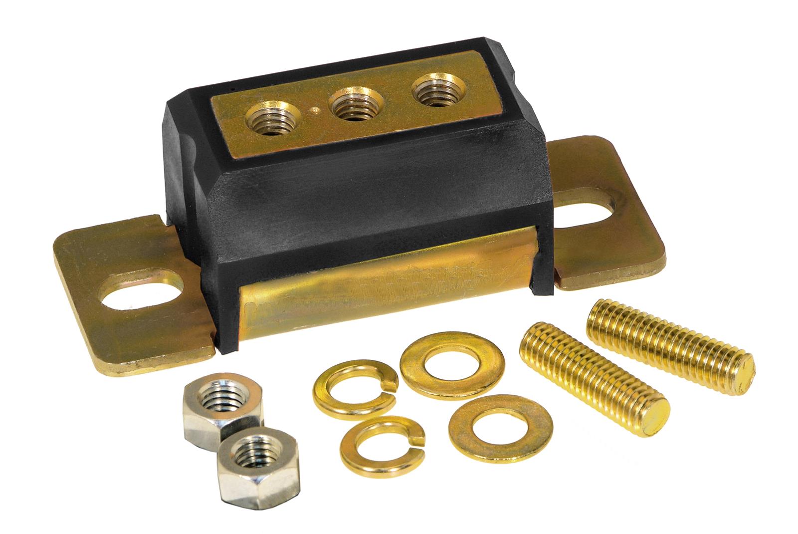
In order to reduce NVH, I steered away from super solid poly bushings. For the motor mount isolators, I'm using Bimmerworld's Group N Replica mounts. Plenty of guys seem to be running these on track with great results, including E92M guys on slicks. At the transmission, I'm using a Prothane Motion Control isolator - still poly, yes, but a relatively soft durometer that will hopefully strike a balance between stiffness and NVH control.

Reproduction mounts are now available, built from heavy duty fixturing to ensure fitment and dimensional accuracy. Tig welded DOM tubing construction.


Hello Chuck
ReplyDeleteNot sure if my previous email made it thru but I like your mount, LSx into E36 and would like to purchase a set, do you sell these babies on the open market?
Regards Matt
Hey Matt,
DeleteSorry if I missed your previous message. Please send me an email at cskovach@gmail.com to discuss.
-Chuck
This comment has been removed by the author.
ReplyDeleteHey Chuck.
ReplyDeleteI dropped you an email about your mounts.
Hope to hear back from you. Really like your design over others I've been looking at. Getting ready to start my LSX swap into my 98 E36 M3.
-Chris
Trying to see if you still make these mounts? I emailed you at the above posted email.
ReplyDeleteChris W
Are these still available? Can they be used with rubber mounts for comfort?
ReplyDeleteHey mate do you happen to have a design plan for these or make them to sell? I'd even pay for the designs for them. Bout to start my build and having trouble getting engine mounts where I live. Thanks buddy
ReplyDelete