Been a little while since an update, but I've been busy.
Engine
Still working on the motor - it's about 90% done. All the details are documented in my build thread here:
http://ls1tech.com/forums/generation-iii-internal-engine/1622786-my-347ci-build.html.
Latest progress: I set rocker height, measured for pushrod length, and ordered a pair of "sample" pushrods to verify my measurements before I order the whole set - looking for trends that may suggest there's some bias to my measurements.
Setting rocker height with shim to obtain narrow and centered contact patch on valve tip through lift:
Measuring for pushrods accurately was kind of a project of its own. The comp checker tools are basically an expanding threaded rod that ranges in length from 6.800 to 7.800. Each full turn gives you ~ 0.050" in length extension. The general procedure is to expand the checker until you reach zero lash at the rocker, count the turns, and then add your desired lifter preload to that. The problem is that you have no precise way of measuring where you are in that last turn - and with a preload target of 0.025-0.030" on my lifters, I'd have no chance in hell at hitting it by using such an imprecise method. This is probably the most common method of those that measure at all - and those guys will almost always come back after their H/C/I install complaining about valvetrain noise. It's because they really have no idea how much they've preloaded their lifters.
The checker tool:
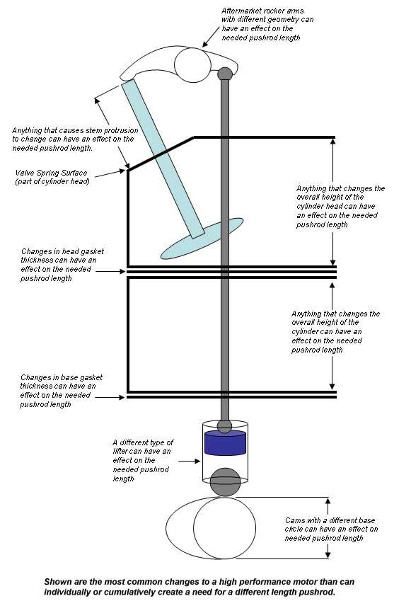
A nifty cross section of all the parts at play that influence pushrod length:
Given all those variables, I facepalm so fucking hard whenever guys just throw in 7.400" comp magnum 5/16" rods and call it good.
What I ended up doing was measuring the "gauge length" of the pushrod manually. This is defined by the distance between the .140" diameters at each ball end - and is slightly shorter than what the overall length would be. The idea is that this removes the influence of the oil passage which range in size and "clip" the full radius of the ball end.
To begin, I verified the calibration on my 8" mitutoyo calipers by using a range of mic standards at work. They measured pretty consistently between -.001" and -0.002" short through the measurement range.
To intersect the ball ends at exactly that .140" diameter (or as close as I could), I drilled holes in a couple pieces of steel with a #28 drill bit (.140x" diameter) and glued them to the jaws of the calipers with 3M Photomount adhesive.
Then I'd measure the pushrod checker, seating the ball ends in the holes I drilled in the steel. This theoretically would give me the true gauge length of the checker. Fully closed, the checker is supposed to measure 6.800". My setup resulted in repeatable 6.798" measurements. So I've got -0.002" bias, assuming that the Comp checker tool has no error (and it does, but my hands are tied because I have no way of quantifying it).
The point of all of this is to identify all of my sources of measurement error in order to produce the most accurate results I can. So far I've got:
- -0.002" accuracy of the tool
- -0.002" offset from "correct" gauge length
The accuracy of the tool itself doesn't matter because my measurements are a relative measurement - meaning my baseline with the jaws closed against the washers has error too. The error of the tool ends up being cancelled out in this instance.
Measuring the checker. Once I got close to zero lash it became necessary to secure the threads with some tape to prevent rotation when removing from the block.
I measured each valve several times over the span of a few days. My results were pretty repeatable - most of the variance attributed to my "feel" for what zero lash was. But in general I was within +/- 0.002". Yea I know it's a big picture. Deal with it.
To verify my measurements with lifter preload, I ordered a pair from Trend Performance - custom length 3/8"-5/16" double taper ball ends with .135" walls. Basically the stiffest option that will clear the heads - about 90% as stiff as full 3/8" rods but lighter. Got them in 7.700 and 7.730 to allow me to check 4 valves each and give me a broader data set to make decisions from. Nice pieces.
So with that I'm trying to verify lifter preload by indicating on the pushrod side of the rocker as I torque it down. Results have been extremely inconclusive thus far because it's extremely difficult to get repeatable measurements. To try and combat this, I ordered more of a pointed indicator tip that will hopefully seat itself in the oil passage and keep it from shifting around as the rocker articulates.
This is where I've left off - I got frustrated with this and am taking a break from it. I left off with a mockup of the motor to try and visualize how things would come together. Not bad.
Car Stuff
In other news, I've been preparing all my suspension parts for sandblasting and powdercoat. I used POR15 on most of the stuff on the original overhaul I did 3-4 years ago now but it did not last. I followed their instructions to a T with sandblasting and the pre-paint metal etch but moisture still got under the paint. Which is why I'm going to try powdercoating this time around.
New additions: M3 rear trailing arms and rear brakes.
Bushings and ball joints pressed out, parts adding up ready to be blasted and coated. Upper rear control arms, rear trailing arms, front control arms, rear springs, trailing arm toe brackets, front subframe, rear subframe, chassis X-brace, rear brake calipers and guides, and a bunch of other random shit that I'm probably forgetting.
I'm going to powdercoat my coilover housings as well - but the threads are seized up and I've been unable to free them yet. Pretty much trashed the aluminum lock collars try to get it apart. Currently they're sitting on my bench soaked in Kroil. It's amazing how unreliable some of these coatings can be.
I also ordered some bar stock of various materials to make myself some replacement bushings and guides. The front diff mount (delrin) in my rear subframe got pretty chewed up after a couple years and they don't sell individual replacements, so I'll be turning my own.
I'll also be making my own rear calipers guide bushings. A stock setup has rubber bushings that allows the caliper to twist - and an aftermarket solution using brass bushings / guide pins to constrain the motion along a single axis. Gives a much more positive pedal feel as well as more even pad / rotor wear when driven hard. The problem with the brass bushings is that they are not sealed and require frequent lubrication to prevent seizing and sever corrosion issues. If the steel pins corrode, the brass bushings get eaten up. So I'm going to turn my own extended bushings that have a threaded end on them for fitment of a cap. Fitment will be challenging but I'm hoping that this will help to keep contaminants out of the joint.
This is what they look like:
and fit like so. The pins are stationary relative to the hub - the caliper floats in and out as necessary.
Box of materials, left to right:
- UHMW rod, going to use as caliper guide pin caps. Impact resistant, chemical resistant, self-lubricating and good to 180 degrees F.
- Bronze bearing grade alloy 544 - impregnated with SAE30wt oil for applications where lubrication is intermittent. Will be used for caliper guide pin bushings.
- Aluminum 6061-T6 tube for insert of front diff mount. Needed to be bigger anyway for fitment of a M14 bolt.
- Black acetal delrin for making the mount itself. Aluminum piece will be pressed / glued into the delrin.
Metal Work
I've also been gearing up for all of the patch panel work still to be done on the chassis.
As a first step, I bought myself a HF bead roller than I've been in the process of hotrodding over the past few weeks. I wanted to be able to add features into flat panels like floor pans to really stiffen things up and help enhance the rigidity of the car.
Obvious problems: it doesn't have a mount and the ears spread apart under load.
Welding angle iron to the back of the plate. I really needed more amperage to get better penetration on the 3/8" plate - I have my little 115v Hobart maxed out. Could have either grooved it out and/or added preheat but I was lazy. Since my life does not depend upon this weld and I was not exactly in need of any additional work I welded it up. Angle was welded to top and bottom ears.
Next I bought some 2" tubing to build a frame.
Leveling feet attached to the base using weld nuts:
Support pieces added to stiffen the vertical upright with the remaining steel I had. Wasted very little on this project - even ended up using the mitered 45' pieces I cut off.
Added a spring return for the upper shaft and zirc grease/oil fittings for all of the shaft bearing blocks.
The new and improved Cometic bead roller. Used the aforementioned miters before to mounting some 5" casters. Lets me tip the machine back and wheel it where I need it instead of having to pick it up and carry it everywhere. Also welded some 1/2" pipe to the main support for storage of all my different dies.
It's a start.
There's still a bit of flex in the upper ear - vertically it's extremely stiff but I think it needs a bit more reinforcement to keep from flexing in and out so-to-speak. I'd also like to add a foot operated AC winch motor and gear drive to it to allow for two-handed control of the sheet. The dies need a little polishing up but all in all I'm happy with how it turned out so far. Could certainly do better if I were to start from scratch again but you live and you learn. Such is life.
Cheers,
Chuck